|
Before you begin, (as we've said many times), doing any unauthorized modification on your guitar could void your warranty or decrease its resale value.
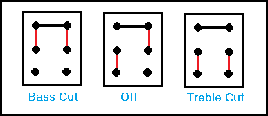
For this circuit, you must use a DPDT on/on/on type of switch . (If you are unsure of which type of switch this is, please go to this page, scroll
down to the DPDT switch section and look at Diagram D.)
When installing the DPDT on/on/on switch, make sure it works exactly the way as depicted in the graphic below.

Building the Circuit
We suggest that you start by soldering all 6 capacitors to the 6 terminals on the rotary switch.
Next, take the free ends of the capacitors you just soldered and twist those around each other, crimp these to the right middle terminal of the DPDT switch and then solder.
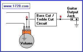
Now (looking at the diagram below), you must cut the "hot" lead from the volume control to the guitar output jack. (these have been labeled A and B).

Now, solder the end of the rotary switch with the attached capacitors to point A then solder the common terminal of the switch to point B.
When using this circuit, the smaller the capacitance value, the more noticeable the bass cut.
The larger the capacitance value, the more noticeable the treble cut.
So, for example, when the rotary switch is set to the .046 mfd capacitor you'll hear a tremendous treble cut, but when you flip the switch it will produce a barely noticeable
bass cut.
Plug your guitar into an amplifier and enjoy the new sounds you just created!
|
| |